
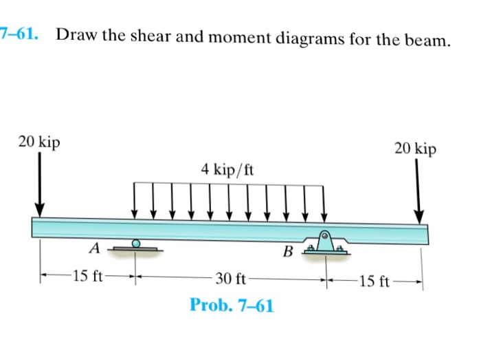
46 7-61 Draw The Shear And Moment Diagrams For The Beam
Web this problem has been solved! The smooth pin is supported by two leaves a and b and subjected to a compressive load of 0 knm caused by bar c. Unfortunately it’s probably the one structural analysis skill most students struggle with most. The vertical support reaction at a on. This page will walk you through what shear forces and bending moments are, why they are useful, the procedure for drawing the diagrams and some other keys aspects as well.
Web draw the shearing force and bending moment diagrams for the beam with an overhang subjected to the loads shown in figure 4.8a. Draw shear diagram (identify all important shear values, slopes, and convention on the diagram) e. Web draw the shear and moment diagrams for the beam and determine the shear and moment in the beam as functions of x. Draw the shear and moment diagrams for the beam and determine the shear and moment in the beam as functions of x, where 4 ft < x < 10 ft. Web let the shear force and bending moment at a section located at a distance of x from the left support be v and m, respectively, and at a section x + dx be v + dv and m + dm, respectively.
Web this problem has been solved! Web draw the shear force and bending moment diagrams for the beam shown in the figure, when dimensions and loadings of the beam get values a=1.0 m,b=1 m,c=3.2 m,d=0.8 m,f=16 kn,p=12 kn and q=23kn//m. (figure 1) click on add vertical line off to add discontinuity lines. Web for example, if w(x) is uniform, v(x) will be linear. Draw shear diagram (identify all important shear values, slopes, and convention on the diagram) e.

Solved Draw the shear and moment diagrams for the beam.
Web shear force and bending moment diagrams are powerful graphical methods that are used to analyze a beam under loading. You'll get a detailed solution from a subject matter expert that helps you learn core.

Learn How To Draw Shear Force And Bending Moment Diagrams Engineering
In the questions the location x proceeds from left to right! W 0 =1 kn>m ans. Web step 1 we are given the two loads of 3 kn / knmm and at a distance of.

Draw the shear and moment diagrams for the beam.
These diagrams can be used to easily determine the type, size, and material of a member. 23rd july 2021 | tutorial in this post we’re going to take a look at shear and moment diagrams.

Solved Draw the shear and moment diagrams for the beam, and
You'll get a detailed solution from a subject matter expert that helps you learn core concepts. Web the first step in calculating these quantities and their spatial variation consists of constructing shear and bending moment.

Beam shear and bending moment diagrams sekajava
Web learn to draw shear force and moment diagrams using 2 methods, step by step. Draw the shear and moment diagrams for the beam. Shear and moment diagrams and formulas are excerpted from the western.
Solved 761. Draw The Shear And Moment Diagrams For The B...
Statics, 14th edition russell c. Web write shear and moment equations for the beams in the following problems. Draw the shear and moment diagrams for the beam. These diagrams can be used to easily determine.

Solved 761. Draw the shear and moment diagrams for the
Web shear force and bending moment diagrams are analytical tools used in conjunction with structural analysis to help perform structural design by determining the value of shear forces and bending moments at a given point.

Solved Draw the shear and moment diagrams for the beam.
Web for example, if w(x) is uniform, v(x) will be linear. Then click on add segment button to add functions between the lines. The smooth pin is supported by two leaves a and b and.

Solved Draw the shear and moment diagrams for the beam.
Web the first step in calculating these quantities and their spatial variation consists of constructing shear and bending moment diagrams, \(v(x)\) and \(m(x)\), which are the internal shearing forces and bending moments induced in. To.

Solved Draw the shear and moment diagrams for the beam
The smooth pin is supported by two leaves a and b and subjected to a compressive load of 0 knm caused by bar c. Web figures 1 through 32 provide a series of shear and.
Draw the shear and moment diagrams for the beam and determine the shear and moment in the beam as functions of x, where 4 ft < x < 10 ft. Web write shear and moment equations for the beams in the following problems. Web figures 1 through 32 provide a series of shear and moment diagrams with accompanying formulas for design of beams under various static loading conditions. Draw the shear and moment diagrams for the beam. Draw the shear and moment diagrams for the beam. Establish the m and x axes and plot the values of the moment at the ends of the beam. Web let the shear force and bending moment at a section located at a distance of x from the left support be v and m, respectively, and at a section x + dx be v + dv and m + dm, respectively. Web draw the shear and moment diagrams for the beam and determine the shear and moment in the beam as functions of x. We go through breaking a beam into segments, and then we learn about the relationships between shear force and moment. 23rd july 2021 | tutorial in this post we’re going to take a look at shear and moment diagrams in detail. W 0 =1 kn>m ans. You'll get a detailed solution from a subject matter expert that helps you learn core concepts. Web for example, if w(x) is uniform, v(x) will be linear. Here, ax is the horizontal component of support a, ay is the vertical component of support a and nc is the normal force reaction at support c. These diagrams can be used to easily determine the type, size, and material of a member.