
42 Motor Schematic Drawing
O and x are showing direction of electric current. Web three phase motor connection schematic, power and control wiring installation diagrams. Web leo watts cnc guides, cnc machining, cnc routers, guides key takeaways stepper motor types: Basics 8 aov elementary & block diagram : Basics 10 480 v pump schematic :
Basics 13 valve limit switch legend : Web the choice of the mcc layout depends on many factors as follows: Instead of wiring diagrams, wiring tables can also be used. Web the electric motor operation is based on the following points: The original wiring diagram showed the proper arrangement of windings to create a larger wye system in which there are four equal windings between any two leads.
Motor specifications such as type (e.g. Web leo watts cnc guides, cnc machining, cnc routers, guides key takeaways stepper motor types: This symbol represents a single phase ac synchronous motor. Web the diagram shows how the commutator (in green) and brushes (in red) work together to let current flow to the electromagnet, and also to flip the direction that the electrons are flowing at just the right moment. These diagrams provide a visual representation of the electrical circuitry and components, allowing engineers and technicians to troubleshoot and repair issues more efficiently.

Motors How to Choose an Electric Motor
Basics 8 aov elementary & block diagram : At least one of the two magnetic field is generated by a solenoid carrying a current. Synchronous motors initially starts as an induction motor but. The output.

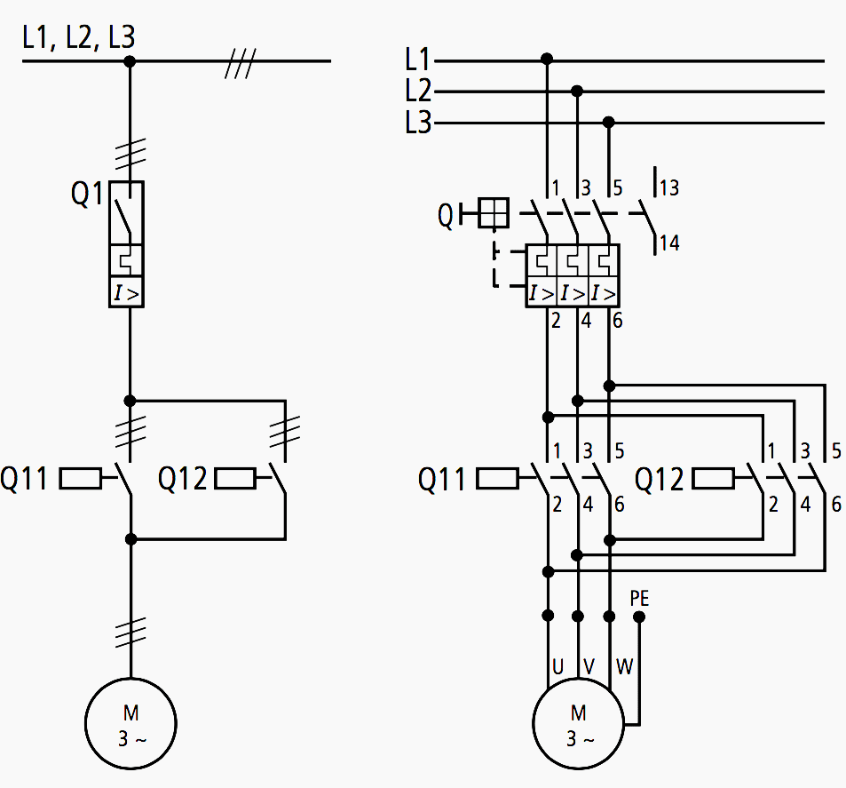
Motor Control Center Schematic Diagram
The same sort of thing. The control circuit may not be at the same voltage as the power circuit. Instead of wiring diagrams, wiring tables can also be used. The original wiring diagram showed the.
All about wiring of electric motors EEP
Synchronous motors initially starts as an induction motor but. Web i remade winding diagram from book, so it fits into my stator. They show the internal and/or external connections but, in general, do not give.

Electric Motor Principle, Working, Diagram Explained step by step
Basics 9 4.16 kv pump schematic : O and x are showing direction of electric current. The same sort of thing. Web line diagrams, also called “ schematic ” or “ elementary ” diagrams, show.

Simple Combustion Engine Diagram Free Image Diagram
Web 10k views 3 years ago motor control. I draw new winding diagram which i had used at winding motor. They do not indicate the physical relationships of the various components in the controller. These.

2 Wire Control Circuit Diagram. Motor Control Basics. Controlling three
Web the image representation of this wiring scheme is easier to visualize. Web motor wiring diagrams. Basics 14 aov schematic (with block. Instead of wiring diagrams, wiring tables can also be used. 4, 5, 6,.

basic for junior marine engineersrammarsea BASIC MARINE DIESEL ENGINES
Web leo watts cnc guides, cnc machining, cnc routers, guides key takeaways stepper motor types: Phase relation between the rotor and stator magnetic field (i.e. Each has different performance and current. Synchronous motors initially starts.

Draw a labelled diagram of an electric motor. Explain its principle and
Squirrel cage, wound rotor, or synchronous), horsepower,. Phase relation between the rotor and stator magnetic field (i.e. Basics 13 valve limit switch legend : Power is supplied by connecting a step down transformer to the.

Mechanical Engineering Engine diagram
Web the diagram shows how the commutator (in green) and brushes (in red) work together to let current flow to the electromagnet, and also to flip the direction that the electrons are flowing at just.

Internal Combustion Engine Block Diagram Free Image Diagram
Web the electric motor operation is based on the following points: Basics 8 aov elementary & block diagram : The same sort of thing. 6 and 8 wires are changeable. This diagrams uses symbols to.
The same sort of thing. The original wiring diagram showed the proper arrangement of windings to create a larger wye system in which there are four equal windings between any two leads. These diagrams are designed to illustrate the flow of electricity and the connections between different parts of the motor. 4 and 5 wires are fixed. Basics 14 aov schematic (with block. These diagrams provide a visual representation of the electrical circuitry and components, allowing engineers and technicians to troubleshoot and repair issues more efficiently. The output of the motor starter goes to a three phase ac motor. They do not indicate the physical relationships of the various components in the controller. O and x are showing direction of electric current. Web line diagrams, also called “ schematic ” or “ elementary ” diagrams, show the circuits which form the basic operation of the controller. Web leo watts cnc guides, cnc machining, cnc routers, guides key takeaways stepper motor types: Motor specifications such as type (e.g. Web the control circuit is separate from the motor circuit. Web motor wiring diagrams. Wiring diagrams show the conductive connections between electrical apparatus.